Non-destructive control of fused cast AZS for high-quality glass melting – Part 2 of 2
How can efficient non-destructive control of fused cast AZS support high-quality glass melting?
Authors: Isabelle Cabodi, Zi Kang Low, Pierrick Vespa – Saint-Gobain Research Provence, Cavaillon, France
Mélanie Allen Larut, Michel Gaubil, Frédéric Pomar – SEFPRO, Le Pontet, France
For more information, don't hesitate to contact us.
Consequences of shrinkage cavity and filling optimization
Theory of filling control
During solidification, as the liquid density of an AZS is lower than solid density, a shrinkage cavity is formed inside the products. According to the block’s filling, from RR to RT (void-free), different rates of residual porosities can be found inside the blocks, affecting them more or less deeply.
The position of porosities is controlled thanks to radar waves: all soldier blocks are scanned thanks to a radar whose frequency is adapted to the controlled material and its thickness. Porosities reflect a part of the signal because they represent interfaces refractory/air. This reflected signal is recorded and thanks to suitable post-processing, porous areas are revealed. Steps of control are described in Fig 8.

For radar results, blocks are divided in 4 areas. Hence a RR-block could have some porosities on bottom quadrants whereas only small residuals porosities can be found on RT-blocks. All soldier blocks are carefully controlled before pre-assembly.
Impact of new trends in glass furnaces
The glass manufacturing market is shifting in two main directions:
- Clearer glass: with a higher transparency, temperature at soldier block bottom is higher than for standard glass.
- Furnace electrification: to reduce emissions of greenhouse gases, electrical boosting and hybrid furnaces are becoming more widespread. The electrodes also trigger an increase in temperature at the block bottom, as well as convection movements.
It has to be kept in mind that a 50°C increase in temperature doubles the corrosion rate. Modeling highlights a new corrosion pattern for soldier blocks as described in Fig 9.

These models have already been confirmed during cold visits of furnaces with increased electrical boosting. A strong corrosion pattern was detected in front of the electrode blocks thanks to 3D scans – see example in Fig 10.

In this case, the gap between the metal line and block bottom corrosion is sharply reduced in this case.
Need for an optimized filling
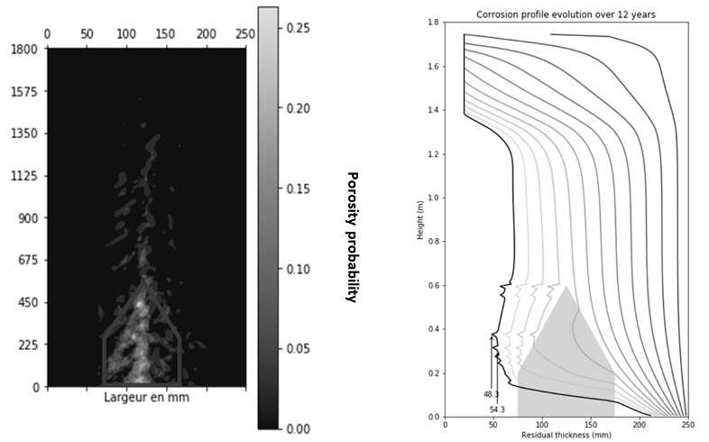
With these growing stresses on refractories, usual RR-blocks will no longer be sufficient in case of really high boosting or extra-clear glass. Indeed, if the shrinkage cavity is reached, accelerated corrosion could occur, leading to a glass leak and associated heavy repairs. Using an extra-clear glass model and a temperature profile in a float furnace to assess the corrosion of an RR-block with an average shrinkage cavity (calculated on 50 blocks), and assuming a corrosion speed 4 times higher in the shrinkage cavity, shrinkage cavity is reached after 11 years as described Fig 11. Each profile represents a corrosion profile after a 1-year increment. After 11 years, it gets strongly faster at the block bottom because the shrinkage cavity is reached.
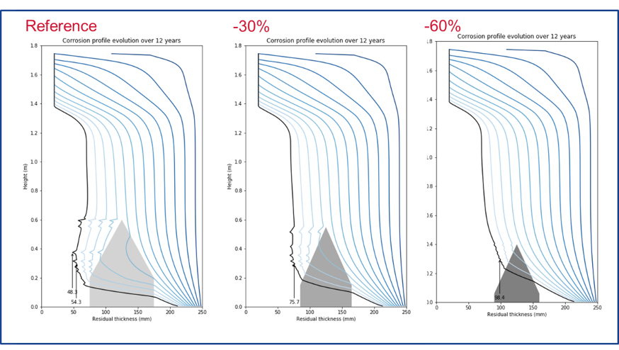
This situation could be worse in case of boosting, or if the extent of the shrinkage cavity is bigger than average. Modeling highlights the strong impact of a modification of shrinkage cavity size (Fig 12.). The corrosion of a block with a better filling will have a far more even profile – three scenarios were tested from a reference RR case to a sixty-percent smaller shrinkage cavity.
Using its large radar analysis database, SEFPRO is developing a sidewall with optimized filling rates allowing a higher performance/cost ratio.
Surface quality – Upcoming improvements
What is surface quality?
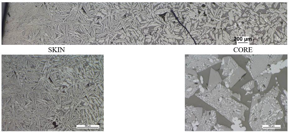
During AZS solidification, different phenomena can affect the microstructure and the aspect of joint faces. First, strong thermal gradients exist between the cold mold and the hot molten AZS. Hence, the skin of the block solidifies rapidly with a columnar structure, whereas the core of the block, with weaker thermal gradients, has an equiaxed structure. Fig 13 shows the difference in microstructure from skin to core.
This difference in microstructure triggers different behaviors in terms of corrosion resistance. Indeed, the finer crystallization leads to a higher tortuosity of the glassy phase, slowing the corrosion of the material. Joint corrosion with a fine microstructure can be 20% smaller than for a coarse microstructure as shown in Fig 14.
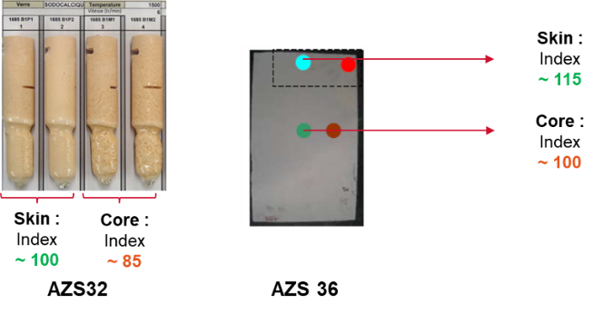
Limit joint faces machining helps to improve furnace lifetime, as it guarantees optimal resistance to corrosion in joints.
Machining is often a way to improve surface appearance, the machining should be limited to the acceptable level of surface defects.
Edge tears are generated by the thermal gradients between cold mold and molten AZS, they are trans-granular surface cracks created at high temperature as shown on the microstructure in Fig 15.

Mechanically speaking, they do not have a major impact on block performances, as they are highly unlikely to propagate during heat-up. Nevertheless, SEFPRO is working on their better understanding to improve the joint aspect.
Finally, in molten AZS, several gazes could be trapped during solidification, from endogenous or exogenous sources. They are responsible for small porosities (bubbles), under the skin of the material, that can be revealed with machining. SEFPRO is also working on limiting as much as possible their occurrence.
Use of image analysis for reproducible measurements
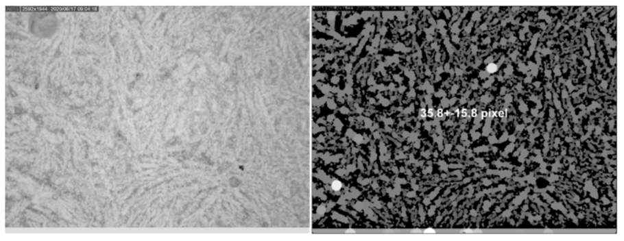
To collect reliable information on microstructure size, bubble concentration, and edge tears presence in a reproducible manner, SEFPRO has worked on identifying and developing sensors. Thus, several techniques have been developed, based on image acquisition and analysis. For microstructure size, a method is under development to acquire information on joint faces with a portable microscope and to give microstructure fineness thanks to suitable processing based on grey-level thresholds and texture parameters. Fig 16. shows the raw image and results from post-processing. Then, the extracted value would be compared to a calibration curve linking corrosion results, thickness machined, and microstructure size.
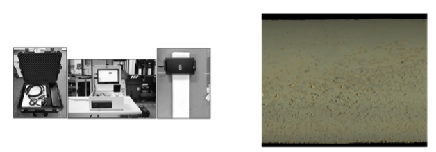
For the joint aspect, contact image sensors (CIS) are used to digitalize joint faces, on a high-definition image. Then, thanks to post-processing based on image analysis, bubble concentration and edge tears can be spotted, following SEFPRO’s specifications. Fig 17 highlights the sensor and the high-definition picture acquired.
Thanks to both tools, SEFPRO is now able to give a better quantification of the joint faces aspect. These controls, currently under deployment, will be available soon on a wide range of AZS products.
Data collection and new product development
Process digitalization enables SEFPRO to build a precise ID card for each block. Combined with NDE controls, it brings sufficient data for several statistical regressions in order to refine process controls and offer products even more suited to the new trends in glass furnaces.
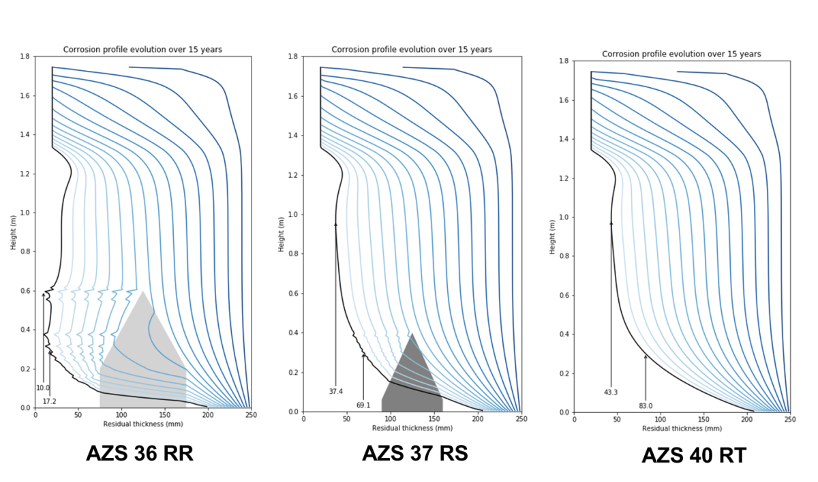
Thanks to data analysis and the improvement of process mastering, the standard AZS range has been split into three products, each of them carefully designed for an application:
- AZS 36 RR, for standard glass applications, with a limited boosting and a usual corrosion profile.
- AZS 37 RS, for clear and extra-clear glass, or in case of a strong boosting or hybrid furnace. This new product has a reinforced filling compared to AZS36 RR. Its chemical composition has been finely tuned for optimal performance. Fig 18 shows a radar scan of such a block.
- AZS 40 RT, which is still the optimal product in terms of corrosion resistance, and to be used in strongly corroded areas.

All these products will also benefit from the latest advances in terms of NDE controls such as color measurements.
The use of AZS 37 RS instead of AZS 36 RR as a soldier block in clear glass should lead to a significant increase in block lifetime and a reduced risk of leakage. AZS 40 RT remains the optimal material. Modeling forecasts are detailed in Fig 18: the most corroded area in extra-clear glass is no longer the block bottom, allowing for easier overcoating operations.
Conclusion
Working on the properties required to maximize AZS quality, SEFPRO has studied and developed several NDE tools. First, color control enables the assessment of blistering and exudation properties, measuring the redox state of products: this NDE has just been deployed on most AZS products. Then, radar controls and tougher specifications are key to limiting corrosion in clear glasses or in the case of a strong electrical boosting. Finally, some further developments are being conducted to monitor the aspect of joint faces. All these NDE studies, carried out with data analysis, recently led to the development of a new product in the AZS range, to address the expectations of new furnaces with clearer glasses or stronger boosting.


Add a Comment