Is Your Weighing System Accurate?
This article is intended to provide а practical, and applications-oriented discussion of the issues involved in weigh system accuracy, and how to estimate the accuracy а particular system might achieve. These discussions are specific to full electronic load cell systems (not lever systems), with state-of-the-art digital scale indicators, as used in automatic batching systems.
Components of weighing accuracy fall into three categories:
- Weighing Apparatus Accuracy - This is the ability of the load cells and the weigh hopper to produce а signal that corresponds to the weight of material in the hopper.
- Digital Scale Indicator Accuracy/Resolution - This is the ability of the weight read-out to convert the load cell signal to an accurate and precise digital reading.
- Automation Repeatability - This is the ability of the automatic control system and weighing apparatus to deliver consistent weighments within a tolerance range to the process.
All three of the above components must be considered when calculating the accuracy of а weighing system, and each will be discussed in more detail below.
The scales used in batching applications consist of the same equipment used in legal for trade applications, where government Weights and Measures organizations approve the scale's accuracy. While the method of stating and measuring accuracy varies from government to government, the generally accepted concept is that the scale should be accurate to .1% of applied load, plus 1 displayed division. In some applications, when the scale is first installed it has to be accurate to .05% of applied load. While batching system scales are not approved for legal for trade, the same accuracy specifications do apply.
Weighing Apparatus Accuracy
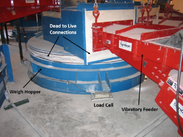
The weighing apparatus consists of the following components (see Figure 1):
- The load cells, which convert force to а voltage output.
- The weigh hopper, which both holds the material to be weighed, and transmits the force to the load cells.
- Dead to live connections. These are unwanted, but necessary mechanical connections between the active part of the scale and surrounding structures (wiring, plumbing, etc.). Properly designed, these connections are flexible, and the inaccuracy they could impose can be mostly designed or calibrated out.

The three items above make up the basic scale apparatus. The most important item relative to accuracy is the load cell. Various government agencies provide type acceptance testing for the accuracy of load cell arrangements. Now we can consider the three following concepts (Load Cell Accuracy, Scale Electronics, and Resolution) and their relationships to how these fundamentals relate to an industrial scale system for Batching.
Load Cell Accuracy
While different agencies state accuracy in different fashions, most test certificates state the accuracy in terms of a percentage of full-scale capacity.
Mathematically the typical expression of accuracy (in the example of a 1000 lb. scale capacity) would be: [ < or = ± 0.02% of rated capacity = [(.02x1000) / 100] = ± 0.2 lbs.].
This is а statement of the expected weighing apparatus accuracy using this load cell to weigh а single material, up to the calibrated capacity of the scale, over the entire temperature range of the load cell.
Scale Electronics, Accuracy and Resolution
What can the scale instrument actually display in regards to the load cells’ measurement capability?
The resolution from the example above when applied through a scale instrument can be expressed as a size, interval, division or granularity (common terms) of the capacity that can be resolved and displayed. Displayed division (dd) is the smallest increment of change (electronic resolution) that can be displayed and updated in weighing systems.
In this case, 1000 lbs. at 0.2 lbs. accuracy would be one part in five thousand (1:5000).
The scale instrument that is used to read and display the load cell output utilizes an analog to digital converter that resolves the linear analog voltage of the cell as a “notched” or “step-change” value.
Modern instruments can have high digital conversion ratios of analog values but typically multi-cell, industrial scales will be set at 1:5000, 1:10,000 and 1:20,000 to obtain stable readings.
Combining these principles:
If a scale system has a full-scale capacity calibrated to 1,000 lbs.; accuracy would be 0.02% of rated capacity or ±0.2 lbs. However, if the scale instrument was set to a stable filter of 1:20,000 (dd), our displayed weight could only show changes of 0.05 lbs. of resolution.
Load Cell Accuracy Related to Batching Systems
The test certificate accuracy specification needs to be interpreted for applications to batching system accuracy for the following reasons:
- In today's batch house designs, the load cells are not subjected to the temperature extremes that are allowed under the specification. Thus, the accuracy will be better.
- The practice of stating accuracy in displayed divisions is related to the concept of the scale being used to weigh а single commodity up to the capacity of the scale. This limitation represents the worst error possible in weighing а single commodity of а weight equal to the scale capacity. It does not address expected accuracy of weighing smaller amounts.
In practice, when Weights and Measures organizations approve а scale installation, they do consider its accuracy in weighing small amounts. They will apply test weights to the scale in incrementally increasing amounts. The error they allow is а percentage of the load on the scale (approximately .05% on а new installation).
Batching systems that weigh multiple materials in а single weigh hopper re-zero the scale at the start of а new material. Thus, the expected accuracy of weighing а single material is а percentage of the weight of that material added to the scale (similar to weights and measures testing а scale with small loads).


An analogy to the incremental accuracy concept would be an automobile speedometer. If the speedometer has an accuracy of 5%, and is currently reading 100 Km/hr., then the automobile’s actual speed is between 95 and 105 Km/hr. - а possible error of 5 Km/hr. If the automobile’s speed is increased until the speedometer reads 105 Km/hr., the accuracy of measuring the CHANGE in the automobile’s speed is 5% of 5Km/hr., or .25 Km/hr., not 5% of 105 Km/hr. Obviously the precision of the speedometer will have an effect on our ability to measure this change in speed to this accuracy, and precision (or resolution) is our next topic.
Digital Scale Indicator Accuracy/Resolution
Another component of а scale's accuracy is the ability of the digital scale indicator to resolve the load cell output into а usable reading. There are several factors involved in this:
- Indicator Sensitivity - This is an indication of the smallest change in load cell output voltage that the Indicator can reliably detect. State of the art indicators have sensitivities better than 0.1 micro volt. Load Cells typically output 30 millivolts full scale, so а state of the art indicator can resolve the load cell rated capacity into 300,000 parts. The sensitivity determines the smallest displayed division size to which the scale can be calibrated.
- Filtering - This is the ability of the Indicator to remove unwanted variations in load cell output due to mechanical vibrations, or electrical noise. State of the art indicators use digital filtering techniques based on discrete fourier transforms, or other digital implementations of analog multiple pole filters. These provide remarkably stable readings in high resolution scales. Typical industrial applications can be calibrated to 20,000 or more displayed divisions (i.e. 0.5#dd in а 10,000# capacity scale), and still provide а stable read-out. The filtering quality determines the smallest displayed division size that the scale can be practically calibrated in.
- Indicator Accuracy - This describes how well the indicator weight read-out corresponds to the load cell voltage coming in. State of the art A/D designs provide better than 0.01% accuracy in this area, much better than the weighing apparatus itself.
In summary, as long as the scale is calibrated to be above .1 uV/dd, and 20,000 or less displayed divisions, the effect of the Digital Scale Indicator on accuracy will be negligible.
Automation Repeatability
The ability of the automatic control equipment to be repeatable in weighing up а specified weight, within tolerance, is dependent on several issues:
- The digital scale indicator needs to be calibrated in а high enough resolution, so that the displayed division size is smaller than the desired tolerance. It is desirable that the tolerance be at least 4 times the division size, although it can be as low as twice the division size in certain circumstances.
- The quality of the material handling feeders, and the flow ability of the material. Vibratory feeders have shown to provide excellent flow control, and predictable cutoff characteristics for most materials.
- The speed at which the material needs to be weighed up. The faster the weigh up, the less repeatable the system will be. If it can be slowed down sufficiently, extremely repeatable weigh ups can be expected.
In а properly configured and tuned control system, а repeatability of +/- 1 displayed division can be achieved in 95% of the weigh ups. For materials where accuracy is not as important as speed, this repeatability would be +/-2 displayed divisions.
Summary
Weights and Measure agencies approve the types of scales used in batching systems for accuracies of 0.02% of capacity, or 0.05% of applied load. Even with the additional dead to live connections found in automated systems, accuracies of 0.1% or better are achievable, although without proper scale installation the dead to live connections can degrade the accuracy considerably.
The ability of state-of-the-art weight indicators to achieve stable readings at 20,000 displayed divisions, coupled with highly repeatable control systems, allow accurate weighments of materials in weights as small as 10% of scale capacity.
EAE Tech specializes in providing automation and process control systems, electrical power distribution systems, quality engineered products, electrical and controls engineering services, and installation solutions that provide our customers with operational upgrades and/or improvements based on their project needs. Let our experienced team assist you with solutions for your upcoming project needs by contacting admin@eaetech.com or call 419-873-0000.


Add a Comment