High Frequency Melting
By: RoMan Manufacturing Inc.
Comparison of an AC IGBT Controlled System and AC Phase Angle SCR Controlled System in a Resistance Heating Application
The Challenge:
To demonstrate electrical efficiency gains with the use of IGBT control technology in comparison to a phase angle fired system in a resistance heating application in an Alternating Current (AC) Application. Gains in Electrical efficiency translate to less power usage and less operating costs.
Background and Definitions:
SCR Control System
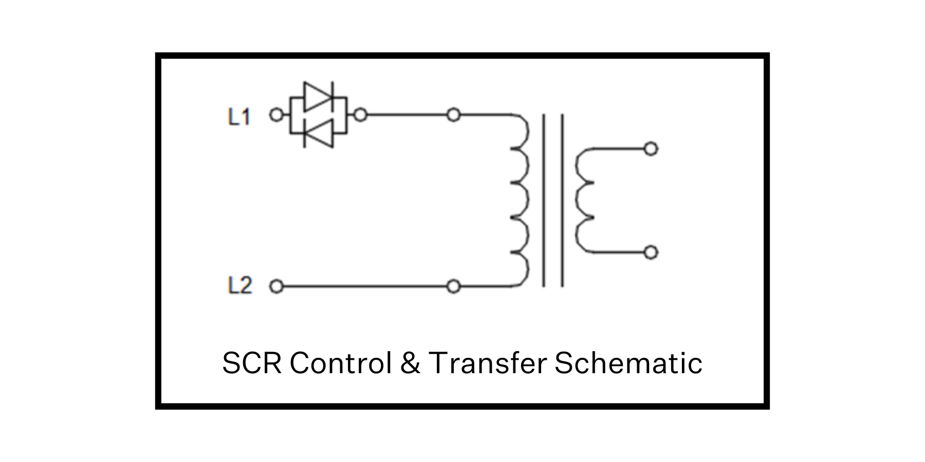
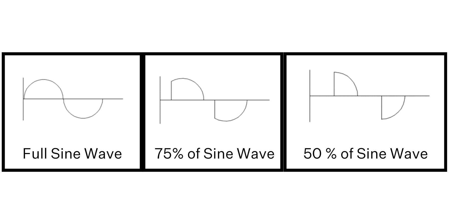
A traditional resistance heating setup uses an SCR (Silicon Controlled Rectifier) which is a pair of thyristors (gated diodes) to control the amount of power applied to the primary of a transformer. The SCR control delays the start of the waveform and the control point is reset when the waveform crosses the zero line.
IGBT Control System
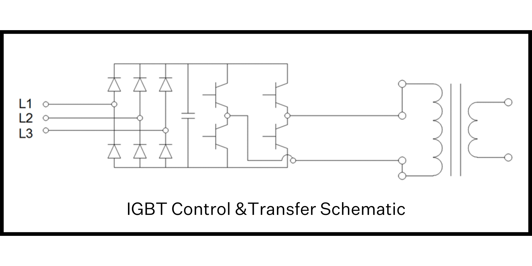
An IGBT (Insulated-Gate Bipolar Transistor) uses a Diode Bridge, Capacitor and Switching Transistors to control the amount of power applied to the primary of a transformer. The input frequency to the transformer is controlled by the switching transistors. Since the IGBT control system utilizes all three phases of the power system, the IGBT control can be set to a particular phase for the zero cross (for phase orientation in the application – Synchronized Mode) or left floating (Non-Synchronized Mode). The input voltage to the transformer is increased by the operation of the IGBT control.
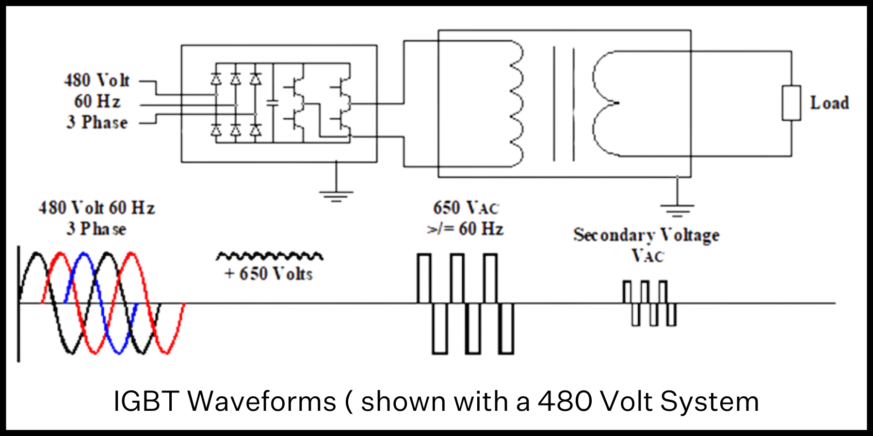
Synchronization with the IGBT can be to the incoming lines (A, B or C phase) and can be offset from each of the phases. The ability to offset from a phase allows for traditional Scott-T arrangements as well as unique offsets allowing for additional vector heating in the application.
Setup:
A stainless-steel load was created for the testing, allowing the load to heat up in the testing process and give a suitable load for power measurements. A transformer was selected for the testing with a wide range of voltage steps to allow for the different primary voltages from each of the control types (IGBT System being greater than the SCR system in output voltage from the control). The primary arrangement and tap specific information are in the tables below. Also below are the schematic representations of both systems for the testing. The IGBT measurements in this paper are with mid-point current control firing method.
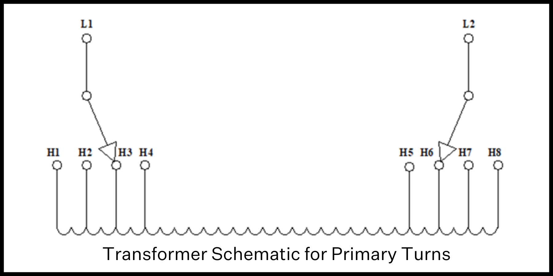
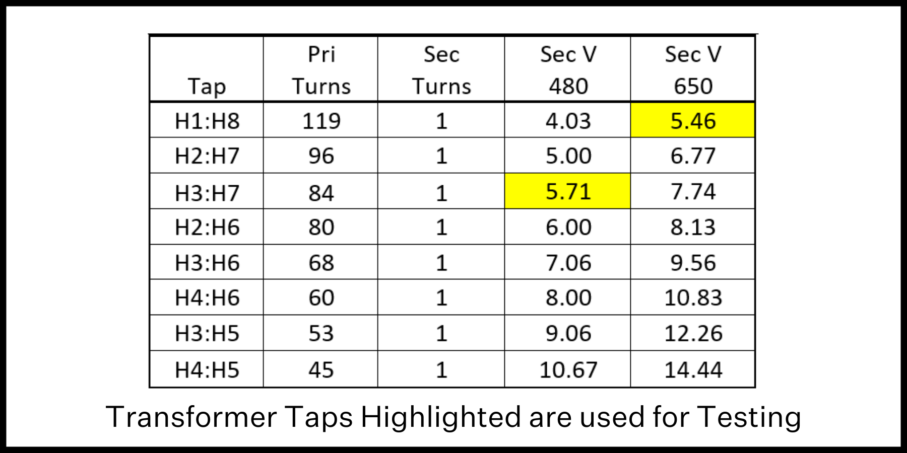
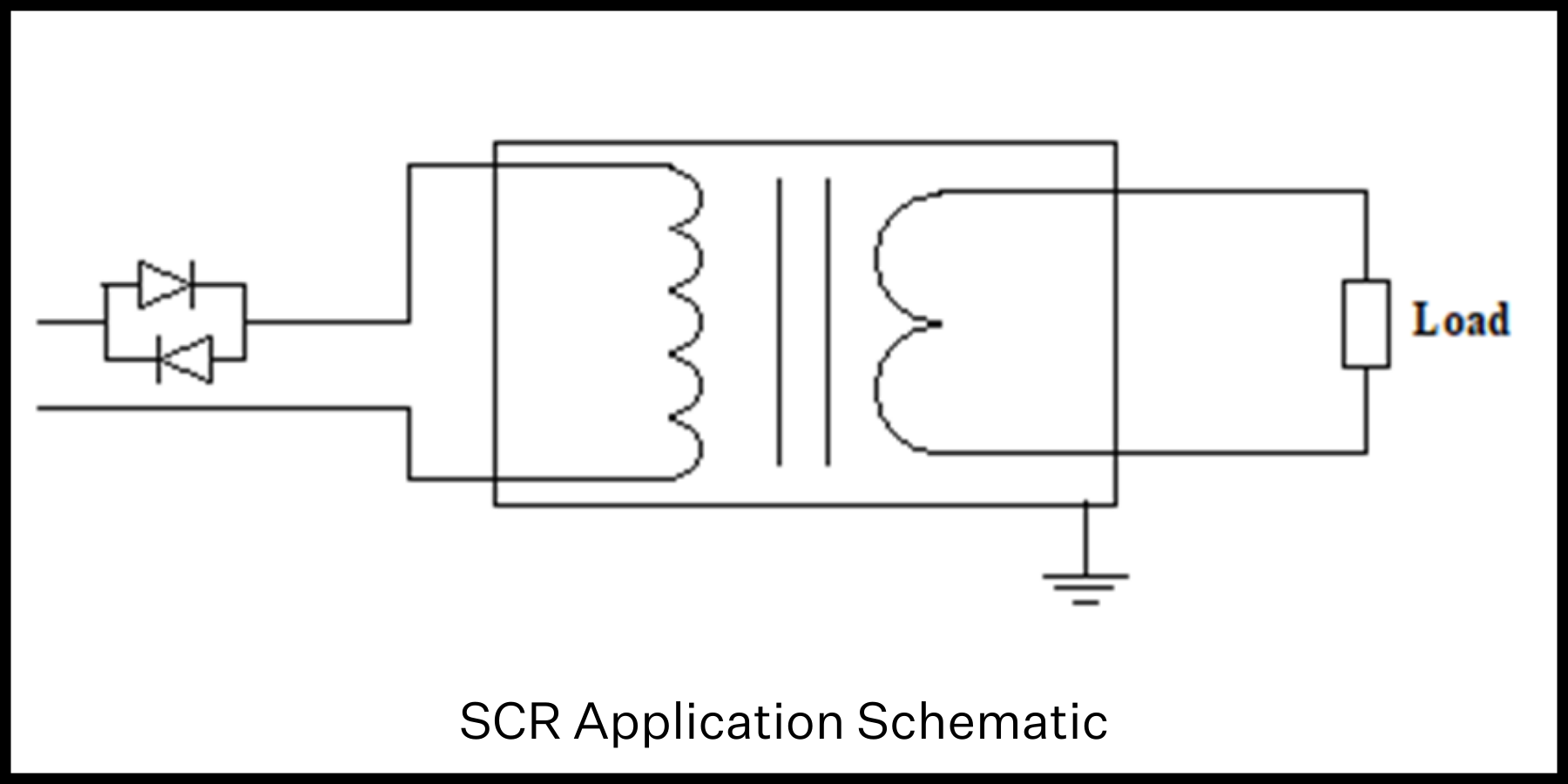
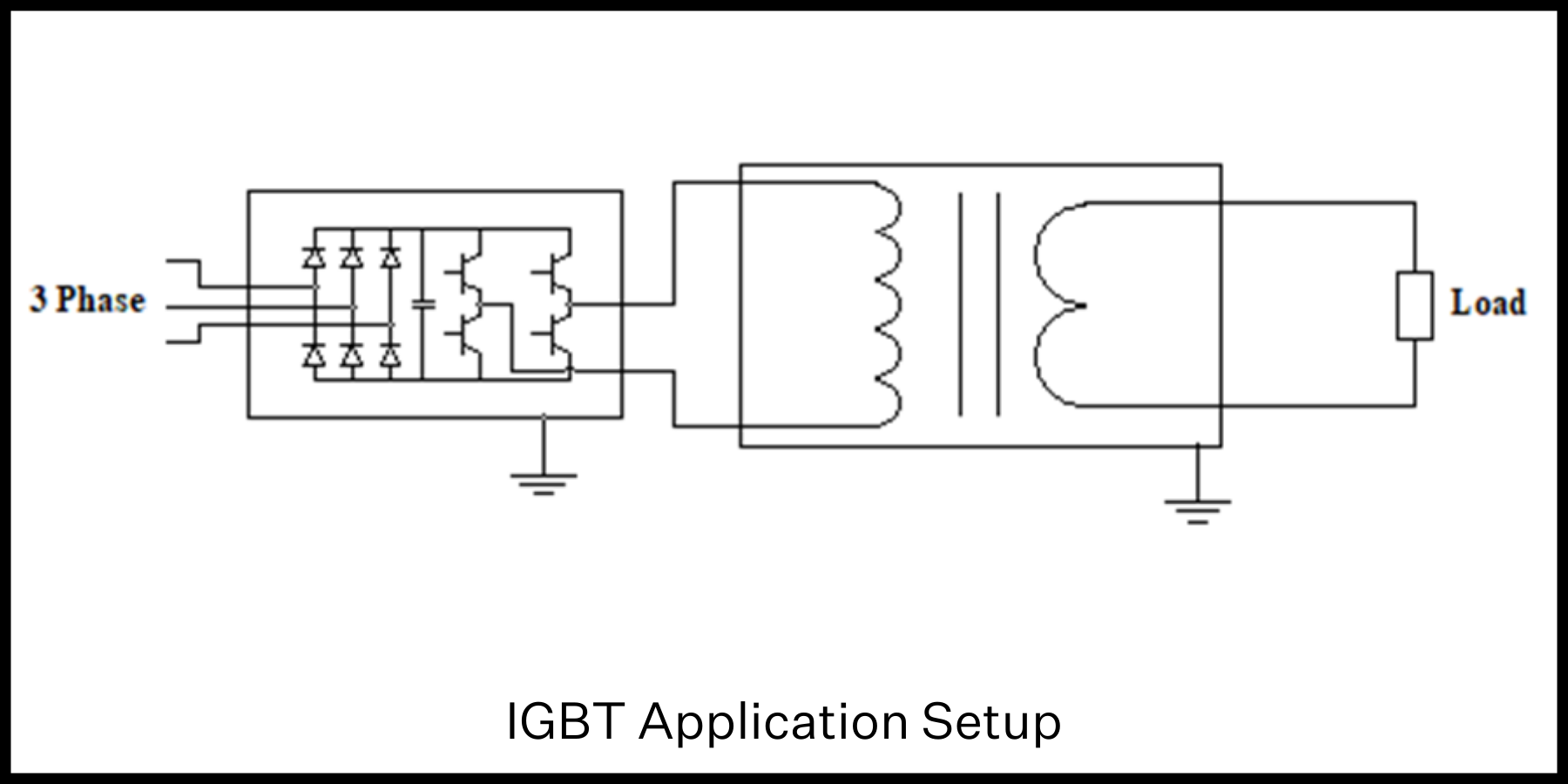
Measurements were taken on the incoming side of the control (what the power system sees in the process), the outgoing side of the transformer and across the load itself for the comparison. The test points for each of the control systems were set at approximately 40, 60, 80 and 100% output for each.
Testing Results:
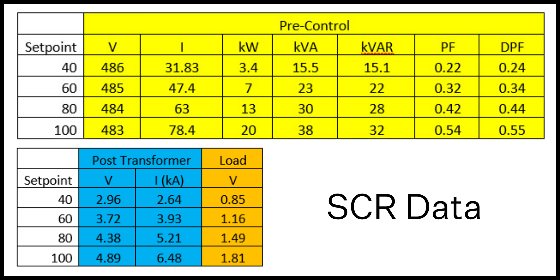
SCR Data:
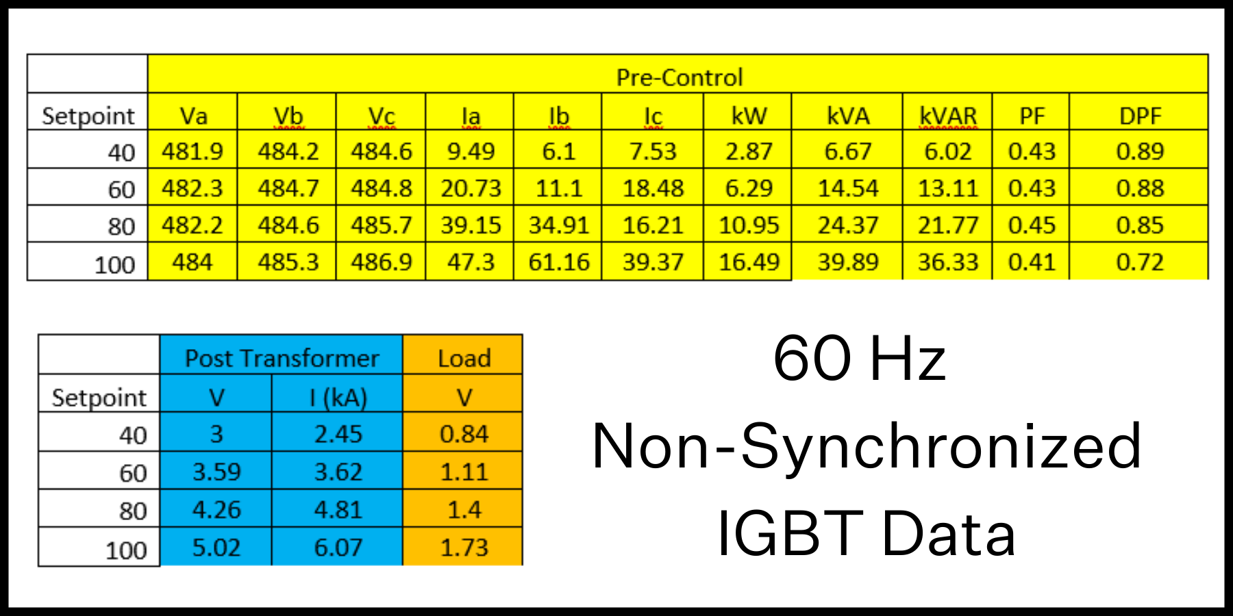
60 Hz Non-Synchronized IGBT Data:
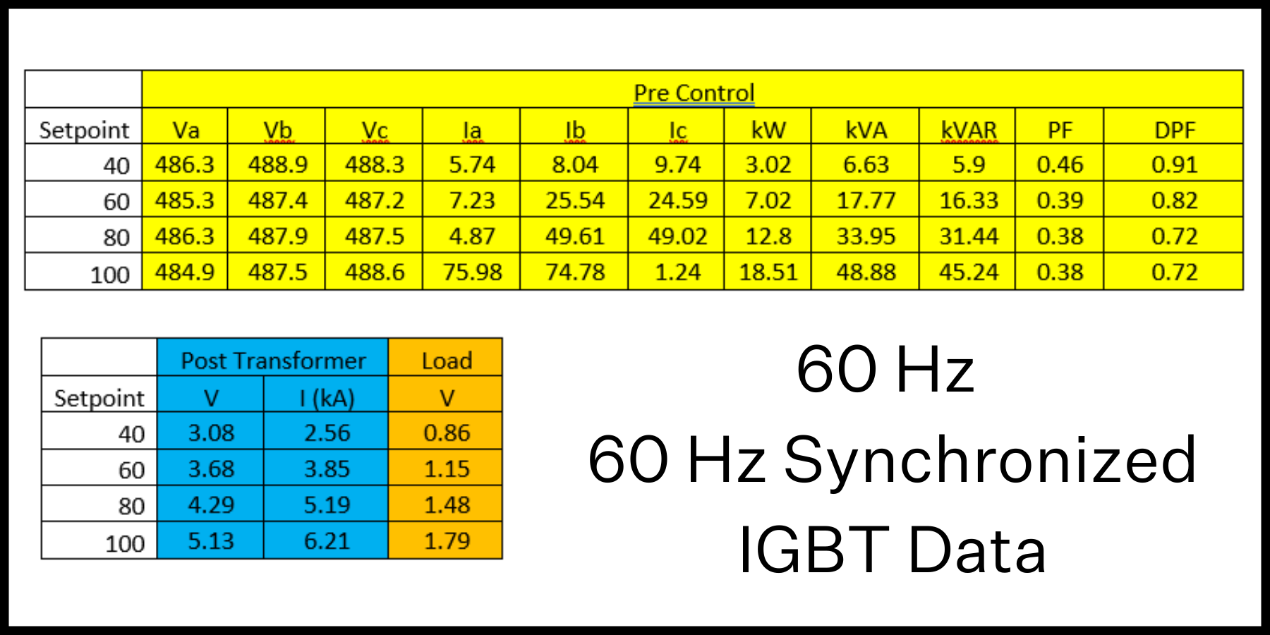
60 Hz Synchronized IGBT Data:
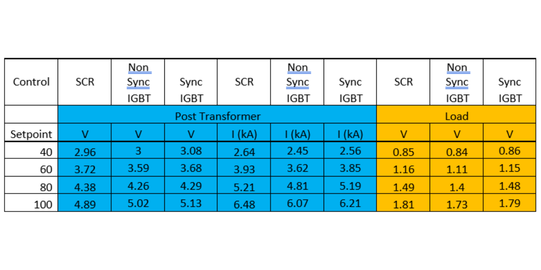
Comparison
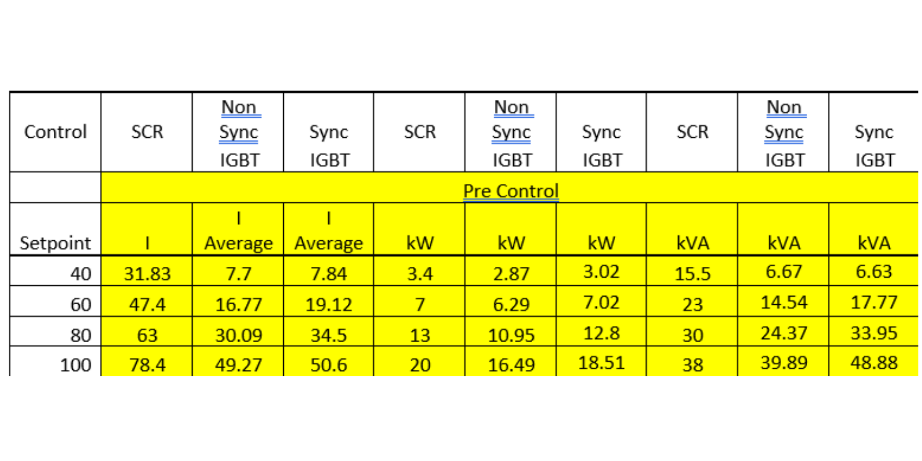
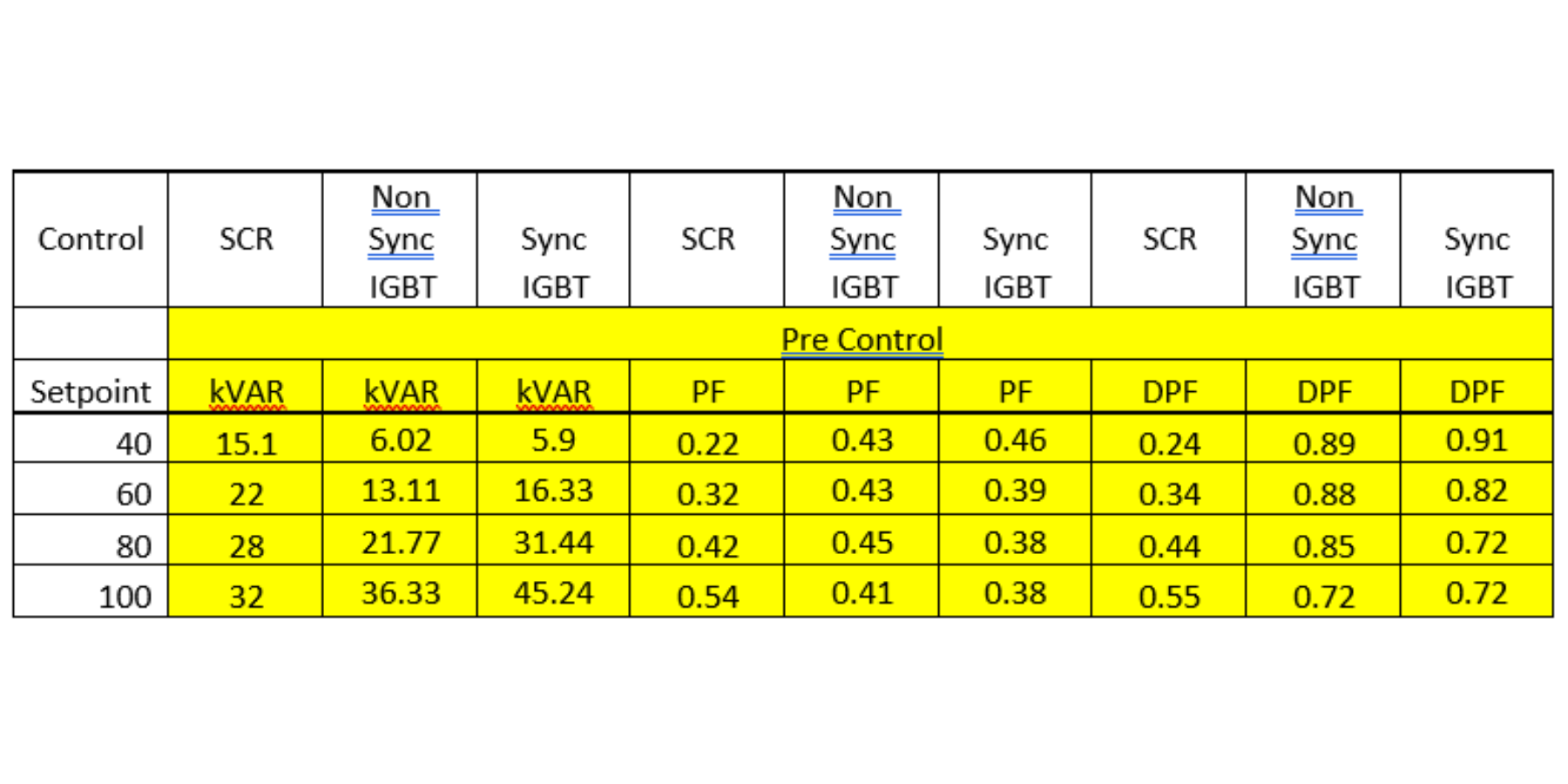
From the perspective of the Load and Output of the transformer the two tests have very similar values so we then look at input values to the system (what the power system sees in terms of usage for the application).
In terms of the aspects of power usage (including averaging the three input currents of the three-phase system with the IGBT control) the IGBT controlled solution has less energy usage in the four test points.
Results and Conclusions:
Results
For the comparisons we will use 40-80% of the setup which allows control of the system (20% headroom for power fluctuations and increased resistance of components from startup due to wear).
Conclusions
In the controlled section of operation (40-80% of waveform used) the following conclusions can be made from the results.
In Non-Synchronized applications
- The Primary Current (I) drawn can be reduced by as much as 58%
- The Real Power (kW) used ban be reduced by as much as 15%
- The Total Power (kVA) can be reduced by as much as 57%
- The Reactive Power (kVAR) can be reduced by as much as 60%
- The Displacement Power Factor (DPF) can be improved by as much as 270%
In Synchronized applications
- The Primary Current (I) drawn can be reduced by as much as 57%
- The Real Power (kW) used ban be reduced by as much as 11%
- The Total Power (kVA) can be reduced by as much as 57%
- The Reactive Power (kVAR) can be reduced by as much as 60%
- The Displacement Power Factor (DPF) can be improved by as much as 279%


Add a Comment