Bottom Leaks in Glass Furnaces
Introduction
Electric boosting is a production proven method of increasing the pull, lowering the specific energy and a path towards “green” production and all electric furnaces. With installing the electrodes through the bottom, this allows the designer the flexibility to optimize the location of the boost power. Some operators will not entertain bottom electrodes due to a fear of catastrophic problems caused by metal inadvertently introduced into the furnace. When tramp metal gets into the furnace it causes accelerated corrosion of the bottom paving and in extreme cases short circuits and damage to electrodes. However, over the last 40 plus years, the production data does not support catastrophic glass leaks attributed to the use of bottom electrodes, especially with the use of KTG SX type electrode holders.
So how does one alleviate this major fear into a minor one? Let’s investigate.
The Wear Mechanism
Molten metal attack on refractories in contact can occur in two ways:
Corrosion - The wear of refractories caused by static chemical attack of the molten metal.
Erosion - The wear caused by the mechanical action of breaking and washing away of refractory materials by molten metal.
This wear can be accelerated by the Marangoni Effect (or convection). The Marangoni Effect is the mass transfer along an interface between two phases due to a gradient of the surface tension. So, how does this apply to glass furnace bottoms? The answer is metal contamination from external cullet. Foreign metal from external cullet creates a three-phase interface between the metal, molten glass and refractory which leads to pitting corrosion (localized holes) and leads to erosion from underneath the refractory blocks.
This phenomenon is often referred to in the glass industry as downward drilling which leads to upward drilling due to bubble formation. When the molten glass flows under the paving brick, bubbles can be produced and rise up to erode the upper refractory bricks. The bigger the bubble the bigger the erosion. This is possible even without bottom electrodes. However, it is the belief that using bottom electrodes that the erosion and corrosion is more accelerated due to higher bottom temperatures or interaction of the metallic melt upon the electrode itself. Hence, the phobia of a glass bottom leak.
Cullet
Two primary trends have emerged in the glass industry regarding the use and handling of cullet. First is the significant increase in the use of external cullet (i.e. brought in cullet), which reduces raw material and melting costs, while lessening refractory erosion and decreasing furnace emissions. Second, the automated handling of cullet has become prevalent, thus reducing manpower and curtailing personnel safety risk.
The Cullet Cycle

Possessing a precise and detailed understanding of the cullet cycle is of paramount importance as we examine the key to higher sustainability in batch plants and cullet handling systems. As shown in Fig 1, cullet processing considerations are intricately interrelated. In many circumstances the material is generated from defective and broken products from the glass plant. However, cullet from recycling operations or external cullet plants now form significant proportions of the container glass and glass fiber batch compositions. While there are some benefits to using more cullet in glassmaking operations, environmental concerns and energy reduction costs are the major elements that are driving the move toward the use of more outside cullet. However, clean cullet without tramp metal is desired.
Metal Removal
Because the cullet supply can provide an excellent path for tramp metals to enter the glass batch,
another important step in the conditioning of cullet for reuse is to magnetically separate unwanted
ferrous tramp metals. Numerous ferrous metal extraction schemes can be considered for this part of the process, such as the magnetic head pulley method, the grid and plate magnetic method, and the overhead and cross-conveyor magnet method. It is also important to remember that some metal removal applications require removal of the non-ferrous tramp metals, which is accomplished with a separate non-ferrous detector and contaminated material removal system. Without metal, there is no accelerated Marangoni corrosion.
Post consumer cullet is no exception to this rule and, therefore, it is incumbant on the cullet suppliers to deliver a chemically and physically consistent product and effectively remove metal impurities.
Electrode Blocks and Holders
One of the biggest arguments against bottom electrodes is interaction with metal contaminates. If this is truly an issue, would it not be seen more often in boosted fuel fired furnaces? There is considerably more fuel fired boosted furnaces in the world than all electric furnaces.
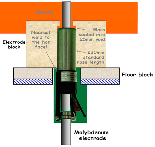
Another concern is a glass leak at the electrode and electrode holder. Advances in electrode designs, such as the KTG Systems SX holder (Figure 2.), and a raised electrode block have eliminated such problems. A raised electrode block stops any perceived risk of an electrical short circuit.
Electrode Cooling Water
Dirty and contaminated process water for electrode holder cooling can be an issue and can cause
possible glass leaks around the electrode holder. KTG supplies a high water specification and a facility may also put strainers before the holder. These will require routine maintenance. KTG also can supply an independent closed loop water system. It all comes down to the confidence level of the plant with bottom electrodes. As of this writing KTG electrode holders have never experienced a glass leak and are the largest supplier of electrode holders in the world, even with the use of extremely high levels of
(often heavily contaminated) cullet in Europe.


Figure 2: KTG Systems’ production proven electrode holder.
Refractory and Bottom Design
Refractories have had tremendous advances over the years. Previously, the uneven characteristics of the ram and its overall quality was a contributing factor to upward drilling (erosion). The bubble would initiate in the gap between the layers with the erosion in the vertical joints less than that of horizontal joints. So, a properly designed bottom of pavers, joints and ram form a whole protective barrier to prevent glass flowing into the horizontals.
Ram products now have an extremely low porosity and with the pouring and tapping process have effectively resulted in the prevention of glass leakage.
Optimal Joulean Heat Release
Joule heating is defined as the process by which the passage of an electric current through a conductor produces heat and is governed by Joules’ Law and Ohm’s Law which relates to power, voltage, current, resistance and time. When electrically melting glass, the molten glass acts as the resistor and adjusting the spacing of the electrodes, without changing power, will increase or decrease the resistance affecting the Joulean heat release into the glass. Depending on glass compositions, spacing electrodes too far apart can result in unwanted currents and voltages as well as phase imbalances which can have detrimental effects.
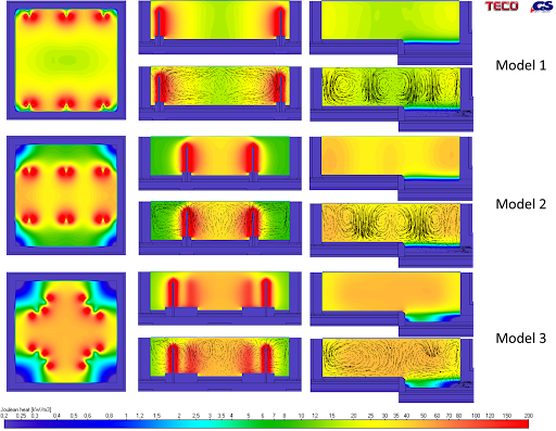
To illustrate the concept of Joulean heat release, a series of models of a square All Electric Furnace (AEF) were developed with varying electrode spacing and arrangements, with the power remaining constant. Model 1 is with electrodes near the sidewalls, Model 2 is with electrodes spaced in thirds and Model 3 is a standard TECO Scott-T design. The results can be seen visually in Figure 3.

Figure 3: Joulean heat release and convective flows.
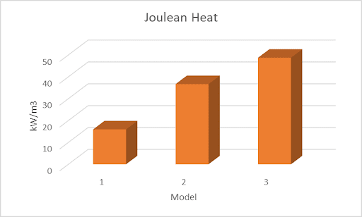
Figure 4 contains the Joulean heat release values measured at the center of the glass melt.

Figure 4: Joulean heat release in kW/m3.
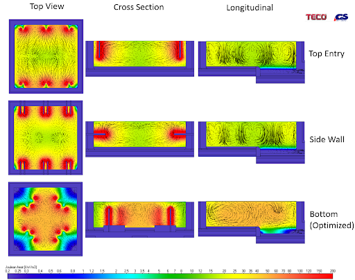
Figure 3 also shows that a good portion of the heating effect is done in close proximity of the electrodes and causes the heat release not to be uniform between the electrodes. This results in convection flows and is a mechanism of melting, mixing and fining of the glass. Figure 5 shows an example of this and the optimization afforded by bottom electrode design. Table 1 contains the results of these parameters. As can be seen, electrode position significantly affects convective flows and an optimal design can only be achieved with the flexibility offered by bottom electrodes.

Figure 5: Optimization of electrical melting system.

Safety, Operation & Maintenance
One of the benefits, often overlooked, is that a furnace with bottom electrodes can easily employ fenced off containment. Enabling state-of-the-art safety cannot be understated. The complete area underneath the furnace around all of the electrodes can be enclosed with redundant access point gates that contain a shut off switch if not properly accessed by limited qualified personnel. Additionally, with all of the electrode access being underneath, it allows for accessibility and far less clutter around the remainder of the furnace.
Sidewall electrodes have to be rotated periodically to prevent them from drooping under their own weight. Secondly, the refractory block is a maintenance wear issue. And lastly, the dimensions of the furnace can be dictated by the electrode spacing. Farther firing path lengths leads to dangerously higher voltage levels and higher voltages leads to changes in power grids and electrical codes.
Top entry electrodes have additional operational issues not found with bottom electrodes which is batch charging and accurate electrode positioning. Top entry electrodes impede the use of x-y batch chargers. For top electrode melters, the common method of charging is from the using a rotational spreader or rotating crown resulting in uneven batch coverage and dust hazards. If molybdenum electrodes are exposed to the atmosphere, they will oxidize quickly and fall off in to the glass. Not all top entry electrodes are located along the sidewalls but can move within the glass area. For example, in the case of a delta or star phasing arrangement, getting these triangular arrangements accurate is often tricky and non-symmetrical power results. Also, with electrode position, in relationship to sidewalls, comes design limitations of AEF lengths and widths. Too large an electrode spacing and improper phasing results in higher operating costs and high boosting voltages. Bottom electrodes are also subject to “tricky” positioning, but unlike top entry electrodes their positions cannot be changed.
Summary
The benefits of bottom electrodes out-weighs any fear of potential glass leaks. Whilst the potential for a glass leak is always a concern and possibility, bottom electrodes and holders do not necessarily warrant a greater concern than that of side electrodes and holders. This is especially the case with a boost system designed and engineered by TECO and KTG Systems.
Production Proven
For real life experiences, check out the article “A Production Point of View “within this issue.


Add a Comment